16th Nov 2020
A few months ago, I decided to design and build a light stick, having seen some videos on YouTube in which similar tools were used for light painting.
I also discovered that you can get addressable LED strips – having multiple LEDs which can be individually controlled not only to turn on and off, but also the colours can be controlled. Furthermore, I found that such strips can be controlled by an Arduino controller. Next, I saw if there is a controller small enough to be accommodated in something the size of a typical handle, and such a controller exists. Finally, can all this be powered by batteries, or does it have to be mains powered.
I found videos online that suggested it was possible to power it with AA-size batteries, and even better, I could source a battery holder to hold 4 AA-size batteries, that can fit into the handle.
You could say some of the inspiration for the light stick came from the weapon of a Jedi in the Star Wars films, I can see the light stick being called a lightsaber.
The following are the electronic components that I was going to need:
- An addressable LED strip
- An Arduino Nano Every
- A PCB, to hold the Arduino, and to facilitate connections to the other components
- A battery holder, to hold 4 AA-size batteries
- An on/off switch
I also got a breadboard and some jumper wires, so that I could put together a representation of the electronic components, and satisfy myself that it will work, before I go embarking on the light stick itself.
The other parts are a 10mm square aluminium bar, 1m long, and some insulating tape, which I will wrap around the bar, before sticking on the LED strip.
Here is the schematic for the light stick.
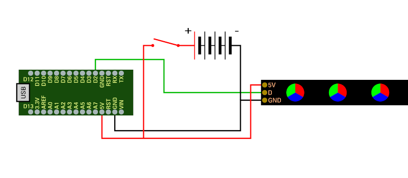
On the schematic above, the red lines represent the positive terminal of the battery pack connected, through the on/off switch to the 5V terminals of the Arduino board and the LED strip. The black lines represent the negative terminal of the battery pack connected to the ground terminals of the board and the LED strip. And the green line represents one of the data terminals on the board, connected to the data terminal on the LED strip.
To program the Arduino board, I had to download two things – first, the Arduino IDE from the Arduino website, and the FastLED library, which is downloaded through the IDE.
Sketches – little programs to control what the Arduino board does, are written with the IDE, which then uploads the sketch to the board.
I set up a layout in line with the schematic, using the jumper wires and breadboard, put 4 AA-size NiMH batteries into the battery holder. It is worth noting that I’m using NiMH batteries, not just because I want to be able to recharge them rather than going out buying new batteries, but because these batteries output 1.2V each. When connected in series, they give a total of 4.8V, which is close enough to the 5V required for the LED strip to function. The non-rechargeable batteries are no good here, because they output 1.5V each, giving a total output of 6V when connected in series, which will destroy the LED strip.
I then wrote a small sketch on the IDE, which I uploaded onto the Arduino board, and unfortunately nothing happened. Having looked online to see what the cause of the problem was, I discovered that the chip on the Arduino Nano Every was not compatible with the LED strip. Fortunately, I came across a small adjustment I could make to one of the files. When I made that adjustment, the LED strip produced light patterns as expected. I have proven the concept.
To make the handle, I had orignally planned to use material that was lying around the house – some unused waste pipe, and wooden pieces for each end of the handle. I quickly realised that this was not going to work, so I looked into the possibility of having the handle 3D-printed. I designed the components of the handle, using Blender, an open-source 3D design package. The handle was modelled in pieces, to facilitate the 3D-printing process, I can put these together later.
The next step was to look for companies providing 3D printing services, as I do not have my own 3D printer. I found one where I could upload a file containing the model of the handle parts, and when I saw that the quote I got back was reasonable, I decided to go for it.
I don’t have much in the way of experience with soldering, so while I was waiting for the handle to be 3D-printed, I did some practice with soldering. When the handle arrived, the next step was to put it all together.
Here are some pictures of the light stick, finished.
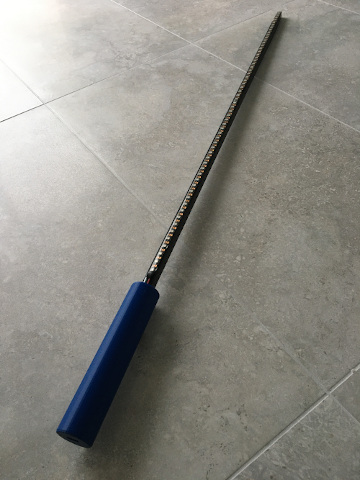
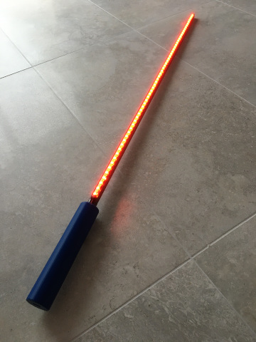
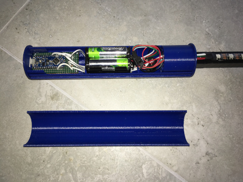
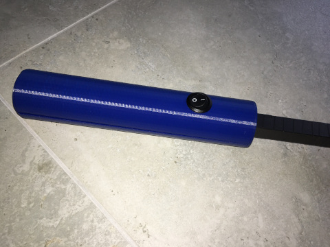
Every time I want to get the light stick to produce a different light sequence, I have to reprogram it, by connecting it to a PC by means of a USB cable, and then upload a new sketch in to it.
While I can make any light pattern I want with the light stick, there is one factor, apart from one’s own imagination that limits things – the amount of memory in the Arduino board. In the case of the Arduino Nano Every, it’s 48 kilobytes. Fortunately the Arduino IDE will give an indication of how much memory the sketch is using when you go to compile and upload it to the board.
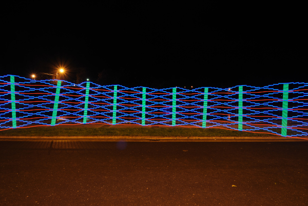
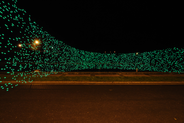
The images below are some examples of light patterns generated by the light stick. This involves putting the camera on a tripod, setting the time to “Bulb” mode, and shutter release mode to remote. I then use the remote to start the exposure, move the light stick in front of the camera to generate the desired pattern, before using the remote to end the exposure.
Sometimes it takes a few tries to get the effect to turn out they way I had in mind.
